This February at FOSDEM, Tsvetan Usunov from Olimex organised a soldering workshop. They gave away free soldering kits of their 1€ RISC-V computer, complete with video, audio and a keyboard input. The workshop was very popular and it ended up closing while I was still in the queue, but Tsvetan gave those remaining in queue the leftover kits to solder at home.
It was a fun kit to solder, all components except the microcontroller are through-hole, making it relatively easy. The MCU is a ch32v003 processor in an SOP8 package. I was surprised that 8 pins would be enough for this purpose, it uses them as follows:
- 2 for power
- 1 for audio
- 2 for keyboard: PS/2 clock and date
- 3 for VGA
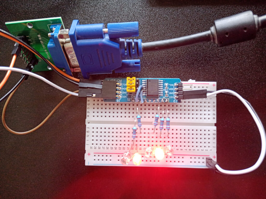
The VGA has 2 clock signals and a video signal. There are small pads to bridge with solder to connect it to a colour of your choice. I chose to connect it to blue and red, to get a purple output. Interestingly, there are no extra ICs on the board, all the I/O is brute-forced by the MCU.
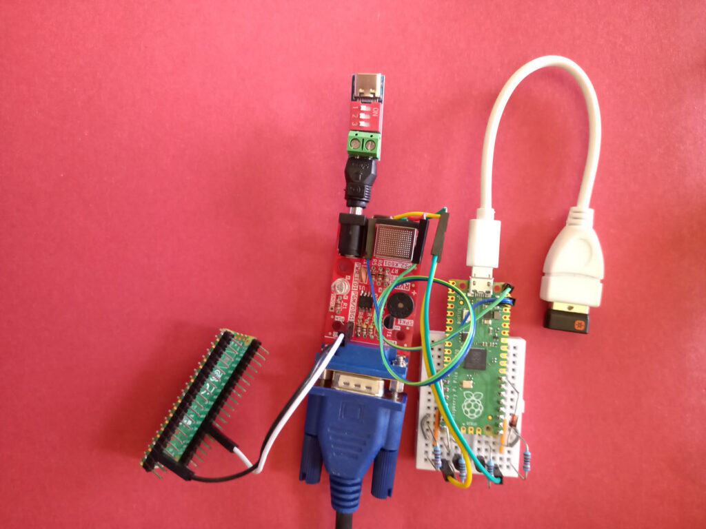
All the hardware and software is publicly available, I had fun looking at the schematics on the github page. By default, it is flashed with a wozmon-like program, but to get there I needed to make some adapters. Here I was happy that I once bought a 10-pack of raspberry picos to reach a volume discount ;).
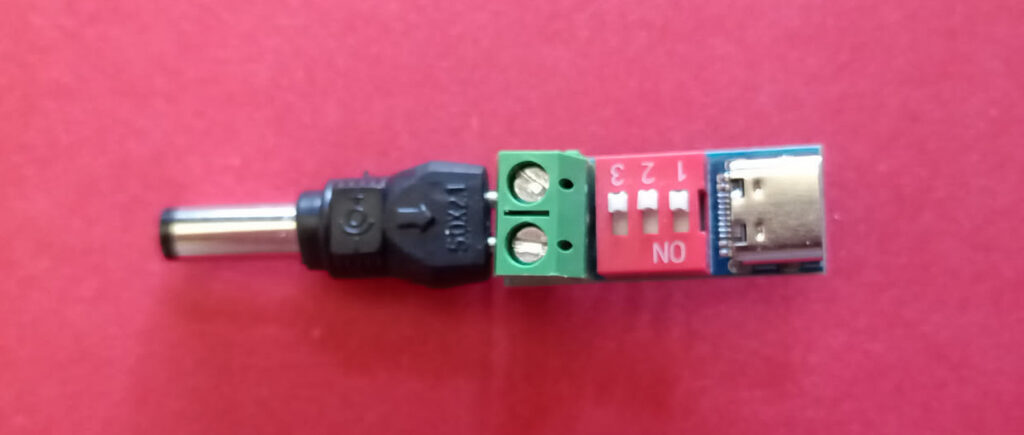
For power, it requires 5V through a barrel jack, although the MCU can also run on 3.3V, maybe the keyboard and VGA would not work properly. As I didn’t have a power supply with the right connector, I made one using a cheap screw-terminal USB-C PD board from aliexpress (hw403) I had laying around and a barrel connector from a universal barrel adapter set. The connections fit right into the screw terminal.
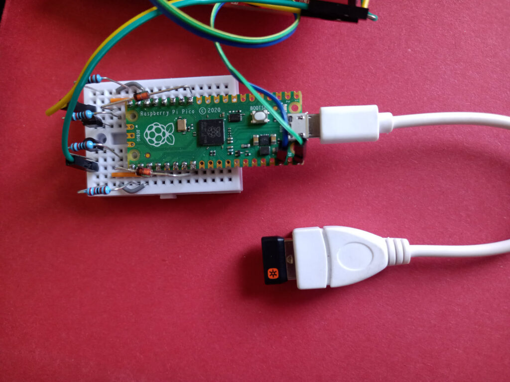
I also didn’t have a PS/2 keyboard available, so I built a ps2pico adapter. Looking at the schematic, I was surprised that I actually understood what was happening, it is an interesting design. It uses 3V zener diodes to bleed away any voltages too high for the pico’s input tolerances, and it worked from the first try.
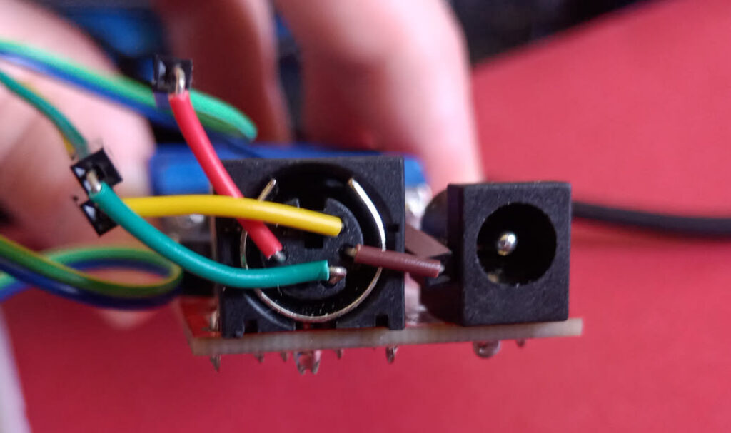
Connecting this to the RVPC was an interesting challenge, I found that the smaller kind of breadboard wire made a good connection, and then used cables with female dupont headers to connect to those.
In order to play with a basic interpreter for the RVPC, I needed to flash new software onto it, but the WCH-link protocol is proprietary, it uses 1 pin that is shared with the keyboard. Luckily someone has reverse engineered it and implemented PicoRVD to use a pico to flash it. All in all, it led to a funny view, with a lot more adapter than computer, and a lot more than 1 Euro of hardware on my desk.
I’ve had great fun playing with this, thanks again to Tsvetan. If anyone else ever finds their keyboard is not working anymore: it is probably the debugger interfering with it as it shares pin 8 with the keyboard clock.
Playing with the basic interpreter I quickly noticed some “limitations”, only room for 3 return addresses on the BASIC GOSUB stack, quite limited resolution on the screen. This got some gears turning in my head, and then I noticed the pins for the VGA HSYNC and video signal also connect to a DMA I2C controller, and that video rendering sure takes a lot of memory and CPU cycles. (foreshadowing)